|
|
|
|
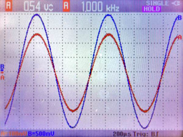
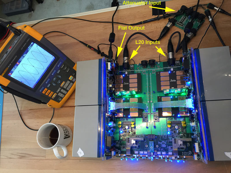
Seta L20 - Small-Signal Sine Wave, 1 kHz to 24 MHz This is a frequency response measurement. The 1 kHz output level is used as the baseline. Output level diminishes as the bandwidth limit is approached. The amplitude measurement precision and accuracy are limited by the 'scope's 8-bit ADC. The practical accuracy for measurements made in this way is within about 0.2 dB, which is sufficient for this purpose.
1 kHz
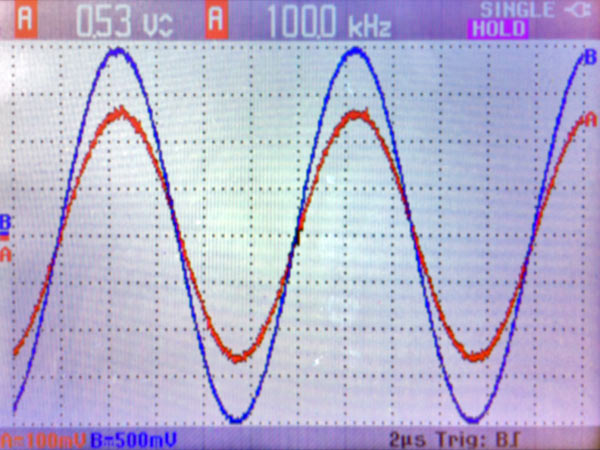
100 kHz
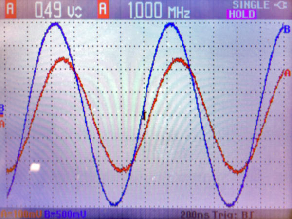
1 MHz (1000 kHz)
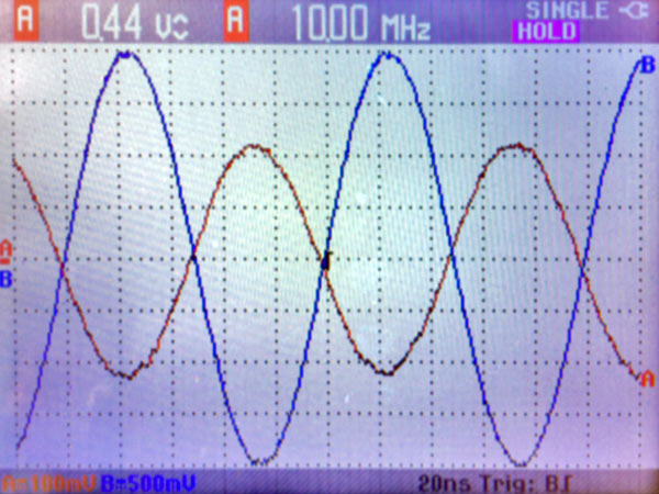
10 MHz (10000 kHz)
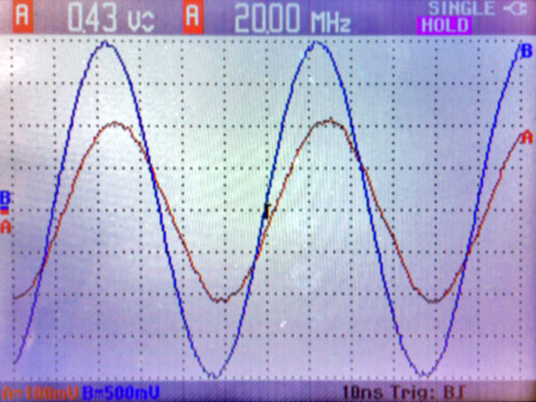
Notice that the signal phase is inverted with respect to the input signal at this extremely high frequency. This roughly corresponds to the signal propagation delay through the L20, about 50 nanoseconds (the reciprocal of one half the wavelength, since delay is one-half cycle or 180 degrees out of phase at this frequency). See the Signal Propagation Delay measurement for another way to determine the signal propagation delay. 20 MHz (20000 kHz)
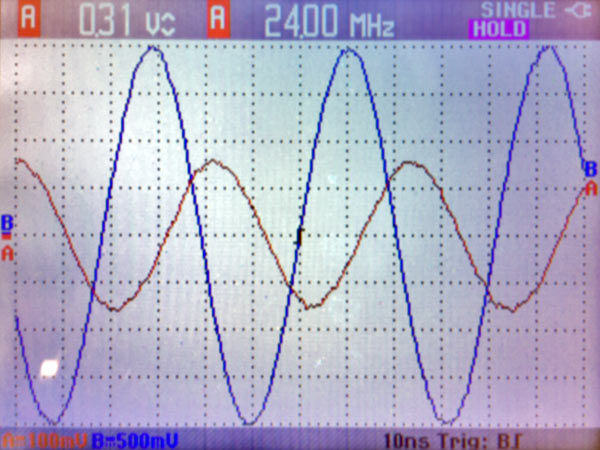
The L20 is specified to have a bandwidth of DC to 20 MHz. Amplifier bandwidth is customarily defined as the -3 dB response point. This measurement determines that the bandwidth of the Seta L20 is somewhat greater than 20 MHz. 24 MHz (24000 kHz)
Here, we are beyond the L20's specified 20 MHz bandwidth limit. A rapid roll-off above 20 MHz is a deliberate part of the L20 design. There also is additional phase shift caused by the roll-off. Links to other Seta L20 measurements
|