|
|
|
|
Seta L20 - Signal Propagation Delay Measurement
Signal Propagation Delay MeasurementWe’ll consider two primary components contributing to signal propagation delay:
High frequency phase shift adds additional delay to the signal, and is confined to frequencies near and above the amplifier bandwidth limit. The measurements below focus on the constant delay portion of the measurement. The phase shift delay can be seen in the measurements of the L20 amplifier bandwidth at 20 MHz and higher frequencies.
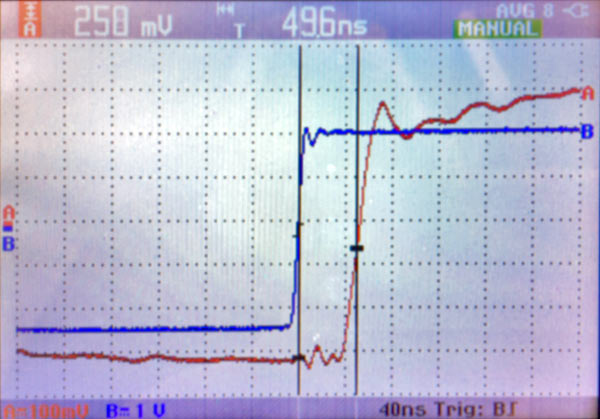
The traces above show that the input to output signal propagation delay is 49.6 nanoseconds. The test signal was a 1 MHz square wave. (A separate measurement, not shown here, determined that about 28 ns of this delay is in the critical front-end circuitry.) This is an outstanding result.
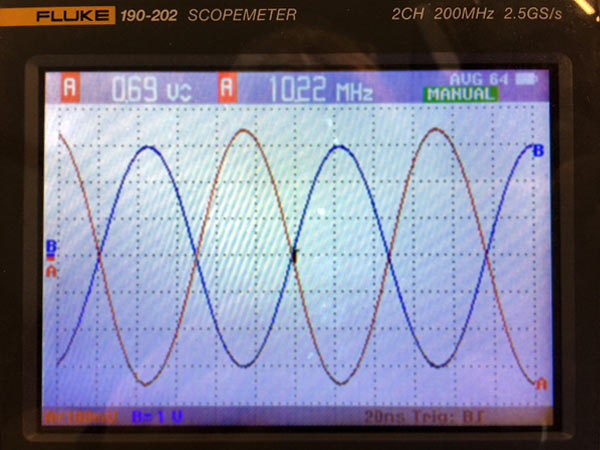
A different measurement used a sine wave adjusted to be the frequency where the output becomes exactly 180 degrees out of phase with the input. The propagation delay is 1/2 the reciprocal of the 10.22 MHz test frequency, or 48.9 nanoseconds, close enough to confirm the other measurement.
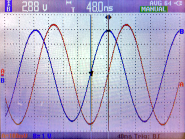
Finally, the square-wave type delay measurement was repeated with a 5 MHz sine wave. The propagation delay measurement result was 48.0 nanoseconds, in close agreement with and confirming the other measurements. With an amplifier this fast, negative feedback's disadvantages are eliminated for audio-frequency signals.A 20 kHz signal (the limit of what's termed audio) has a period of 50 microseconds (50,000 nanoseconds) from wave crest to wave crest. Therefore,A 20 kHz audio signal is over 1000 times slower than the propagation delay of the Seta L20.This illustrates why pursuing extreme frequency bandwidth in an "audio" amplifier is worthwhile. We can use moderate amounts of negative feedback to substantially reduce distortion, and the amplifier will always be running with the feedback and input perfectly "in sync" at all audio frequencies because the amplifier is over 1000 times faster than the fastest audio signal. The input and output are locked together in perfect step. And distortion is lower to begin with because the amplifier is just loafing at audio frequencies. Links to other Seta L20 measurements
|